Excerpts from
Teaching with Documents: Using Primary Sources from the National Archives
National Archives and Records Administration and National Council for the
Social Studies
Washington, D.C.
1989
Maps Using Hachure and Contour Methods
Map makers have traditionally used various means to represent the three dimensions of the earth in two-dimensional images. Prior to the nineteenth century, for example, the most common device for indicating relief on a map was through variations of light and shade.
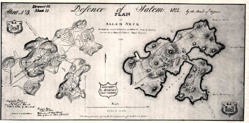
As the use of shading became systematized during the eighteenth and nineteenth centuries, French cartographers referred to these shading lines as "hachures." Hachures represent the slope of the land—the more gentle the slope, the fewer the lines—and the absence of line indicates flat terrain. The illustration on the right side of the document is an example of this system.
The use of contour lines to visually represent different elevations of land came into general use toward the end of the nineteenth century. An early version of a contour map is seen on the left. Simply speaking, a single contour line corresponds to a single elevation of the land. Because the contour line defines a curved surface (the earth), each line encloses a more or less circular area. The total effect is a pattern of concentric lines. The "base" line or datum for most contour maps is sea level, with each line on the map representing a standard distance above or below the base line. As each line signifies an increase or decrease in the land elevation (in this map, 3 feet), one can accurately calculate height by simply counting the lines from the base line (the water's edge in this instance). The slope of any change in the landscape relief can also be determined by noting the proximity of the contour lines to one another. A high concentration of lines tells the map user that the elevation changes sharply, while widely spaced lines indicate a gradual slope.

(Open Map in Separate Browser Window)
The two maps of Salem Neck, Massachusetts, surveyed by George W. Whistler (father of artist James A. McNeill Whistler) and William G. McNeill, topographical engineers for the United States Army, were created for a study conducted in 1822 of fortifications in the area. When the Office of Chief of Engineers decided in 1861 to study the feasibility of reconditioning the forts, they referred to these maps and the reports accompanying them.
This document is part of the records of the Office of the Chief of Engineers, United States Army (Record Group 77, Fortifications file, drawer 18, sheet 11).
Suggestions for Teaching
In order for students to answer the following questions, they must (a) examine the maps closely, (b) familiarize themselves with the scale and accompanying note (located at the bottom center of the document), and (c) understand contour and hachure methods of mapping. (The exercises can be adjusted to meet the needs of your students.)
Maps as Maps—Basic Map Skills:
1. What evidence is there in this document that tells you that the land area is not an island?
2. What descriptive information contained in the map on the right side of the illustration is omitted on the left?
3. Calculate the length and width of Salem Neck in miles.
4. How are points of elevation represented on each of these maps?
5. Using both maps, try to calculate the height of the area where the Alms House is located. Which of the two maps is preferable? Why?
Maps as Historical Documents:
1. What does this document tell you about mapping techniques in 1822?
2. Is there evidence in the document that the map was used after 1822?
3. How might this document have been useful to historians and/or cartographers in the past? How and why might it be used today?
4. Can you find Salem Neck on a contemporary map? Why or why not?